This is part of a series of posts related to My Internet of Things and MobileFirst adventure. An index to all posts can be found at the end of the first post.
Finally, we come to creating the mobile app that will tie this all together. This is going to involve a lot of steps so I will cover the basic outline of what I did without getting into every line of code. You can download all the source files for this project (including the Node-RED flows) from IBM Bluemix DevOps Services if you want to see the details.
But at a high level, here’s what needs to be done:
- Add the IBM Mobile Push service to the Bluemix application. This will manage the push notifications with APNS (Apple Push Notification Service).
- Add nodes to the Bluemix Node-RED flow to initiate a push request when it receives the visitorAlert event. This is how Bluemix will tell the mobile app that the doorbell was pressed.
- Create a MobileFirst project. This will house an adapter that will retrieve the file from Cloudant as well as generate the SDK library the iOS app will use.
- Create a new Xcode project to house the native iOS app
- Add the MobileFirst SDK to the Xcode project.
- Add the Bluemix SDK to the project.
- Write code
Add the IBM Mobile Push service to the Bluemix application
- Open the Bluemix application.
- Click ENABLE APP FOR MOBILE and then YES and then CONTINUE.
- Click ADD A SERVICE OR API and select Push from the Mobile category, then click USE and then RESTAGE. I should point out that there is a Push iOS 8 service as well. I chose not to use it and stuck with the older Push service. Part of the reason was that Push iOS 8 depends on the newer Advanced Mobile Access and I already knew using it would require customizing my Bluemix Node-RED instance to support it. I took the path of least resistance, but at some point, I will need to adopt AMA to keep up with the times.
- At the top of the application’s overview page, you will now see the app’s registration credentials. You will need these later to tell the mobile app how to connect to Bluemix.
Configuring Apple Push is not for the faint of heart. First of all, it requires you to have an Apple Developer license. You can buy a personal license for $99 per year if you don’t have access to a corporate license. Once you have a license, you must use the Apple Developer Portal to create a Device ID, an App ID and a Provisioning Profile as well as an SSL certificate that must be used by any application that wants to request APNS to send a push notification. That process is out of scope for this blog, but you can read about it in the iOS Developer Library.
Once you have your SSL key, you will need to register it with the IBM Bluemix Push Service.
- Go to your Bluemix application and click the Push service.
- Select the Service Mode Sandbox or Production, depending on if you have a Development or Production SSL key from Apple.
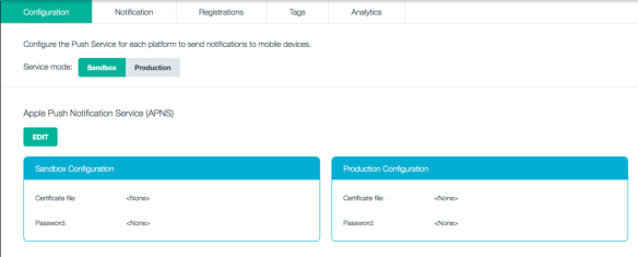
Bluemix Push Dashboard
- Click EDIT under APNS.
- Upload your p12 SSL key and enter the password for it.
It is possible to use the IBM Push dashboard to send out test notifications. This can be helpful in debugging the process.

Bluemix Push Notification tab
Add nodes to Bluemix Node-RED to initiate Push notifications
Node-RED on Bluemix includes nodes for IBM Push. However, I was not able to get them to work as expected. So I chose to go about this through brute force with HTTP nodes. This has the advantage of demonstrating more of the details of how the Bluemix Push SDKs work, but I should really revisit this someday.
- Open your Bluemix Node-Red flow editor.
- Add a function node. Its input should be connected to the output of the visitor Alert Event IBM IoT In node. Name it send notification.
- Add the following code. Yes, I am cheating. the picture filename is not a URL, but I got lazy and decided to use the URL element to pass it.
var newmsg = {};
newmsg.headers = {
    "IBM-Application-Secret" : "<your-secret>" };
newmsg.payload = {
    "message" : {
        "alert"    : "Someone is at the door!  " +
               "Would you like to see who it is?",
        "url"      : msg.payload.pictureFilename
    },
    "settings" : {
        "apns"   : {
            "sound" : "doorbell/Doorbell.mp3"
        }
    },
    "target" : {
        "platforms" : ['A']
        }
};

return newmsg;
- Replace <your-secret> with the value of your application secret code from the application’s overview page.
- Add an http request function node (note – this is not an http input nor http output node). Its input should be connected to the output of the send notification function node.
- Set its method to POST.
- Set the URL to https://mobile.ng.bluemix.net:443/push/v1/apps/<your-appId>/messages where <your-appId> is the application appId found on the overview page.
- Set the return type to UTF-8 String.
- Add debug nodes if you want.

Final Bluemix Node-RED flow
Create a MobileFirst project
I’m going to leverage the IBM MobileFirst Platform Foundation for this mobile application. This is, of course, not necessary to use Bluemix services. You can access Bluemix services directly from an iOS native app. I’m not going to demonstrate them in this tutorial, but the MobileFirst Foundation provides a long list of capabilities that make developing applications easier and more secure. What it does mean is that there will be a server-side component called an adapter that will do the actual Cloudant communication. The iOS app will use the MobileFirst SDK to invoke routines on the adapter.
To create the MobileFirst project, you need to have either the MobileFirst Studio extension to Eclipse or the MobileFirst command line interface installed. I’m going to be using the command line interface here.
- Create a new project from the command line with ‘
mfp create DoorbellIOSNative‘.
- ‘
cd DoorbellIOSNative‘
- Start the mfp Liberty server with ‘
mfp start‘.
- Create an adapter that will retrieve the Cloudant data with ‘
mfp add adapter CloudantAdapter --type http‘.
- Implement the adapter logic. The simplest way to do that is to copy the CloudantAdapter.xml and CloudantAdapter-impl.js files from this MobileFirst tutorial.
- Be sure to edit the domain, username, and password values in the xml file so they reflect the values from your Bluemix overview page.
- Add a new iOS native API using
$ mfp add api APIiOS -e ios. There are two configuration files you need to edit in the project’s /apps/APIiOS folder. Use this MobileFirst tutorial as a guide:
- The worklight.plist file contains several settings that your iOS app will need to know in order to connect to the MobileFirst server which hosts the adapter.
- The application-descriptor.xml file defines the application name, bundleID and version for the MobileFirst server.
- Once you have finished configuring these files, deploy the project to the MobileFirst server with ‘
mfp push‘.
Create an Xcode project
The Xcode project will contain your iOS native app source code. Create a blank project and create an app with a UIImageView to contain the picture. If you are not that comfortable coding, you can download my project from IBM Bluemix DevOps Services. Developing the app UI is not really the focus here, but rather showing how you configure the project to access the MobileFirst adapter and IBM Push from Bluemix.
Add the MobileFirst SDK to the Xcode project
When you created the MobileFirst project above, two things were created that you will need to add to your Xcode project – the worklight.plist file and the WorklightAPI folder. You also need to add several frameworks to the Xcode project to get access to the libraries you will need. The IBM MobileFirst Platform Foundation Knowledge Center does a good job of explaining how to do this.
Add the Bluemix SDK to the project
The SDKs you need for IBM Push are included with a bundle of SDKs for Bluemix. You can download them from the IBM Bluemix Docs. The only tricky part here is that these libraries are Objective-C libraries. Since I coded my iOS app in Swift, I had to create an Objective-C Bridging Header. This is a really easy way to expose Objective-C code to Swift applications.
Write code
There are multiple places in the AppDelegate and ViewController where I needed to add custom code. The two main functions I needed to deal with were configuring the app to receive and handle push notifications and then to use the MobileFirst adapter to retrieve the image.
Push notification configuration
didFinishLaunchingWithOptions
This is sort of the main routine for an iOS application. It is invoked when the app launches. Here is where you need to have the app register for push notifications with the following code:
        // ========================================
        //  Register for push notifications
        // ========================================
        // Check to see if this is an iOS 8 device.
        let iOS8 = floor(NSFoundationVersionNumber) > floor(NSFoundationVersionNumber_iOS_7_1)
        if iOS8 {
            // Register for push in iOS 8
            let settings = UIUserNotificationSettings(forTypes:
                UIUserNotificationType.Alert |
                UIUserNotificationType.Badge |
                UIUserNotificationType.Sound, categories: nil)
            UIApplication.sharedApplication().registerUserNotificationSettings(settings)
            UIApplication.sharedApplication().registerForRemoteNotifications()
        } else {
            // Register for push in iOS 7
            UIApplication.sharedApplication().registerForRemoteNotificationTypes(
                UIRemoteNotificationType.Badge |
                UIRemoteNotificationType.Sound |
                UIRemoteNotificationType.Alert)
        }
Notice that the way you register for push changed with iOS 8 so the code here first determines the OS level, then does what it needs to do.
didRegisterForRemoteNotificationsWithDeviceToken
This method is invoked by the framework when the app has successfully registered with APNS. Here is where you want to initialize the Bluemix and Push SDKs. You would replace the placeholders with the route, appId, and appSecret from your Bluemix application.
        // Initialize the connection to Bluemix services
        IBMBluemix.initializeWithApplicationId(
            "<your-app-id>",
            andApplicationSecret: "<your-app-secret>",
            andApplicationRoute: "<your-app-route>")

        pushService = IBMPush.initializeService()
        if (pushService != nil)  {
            var push = pushService!
            push.registerDevice("testalias",
                withConsumerId: "testconsumerId",
                withDeviceToken: self.myToken).continueWithBlock{task in

                if(task.error() != nil) {
                    println("IBM Push Registration Failure...")
                    println(task.error().description)

                } else {
                    println("IBM Push Registration Success...")
                }
                return nil
            }
        } else {
            println("Push service is nil")
        }
didReceiveRemoteNotification
This method is invoked by the framework whenever a push notification is received. The payload of the push notification is passed in in the userInfo object. In a series of ‘if let’ statements, I extract the bits of information I need. Then I determine if the app was in the background or inactive. If so, that means the user already saw the notice, read it and chose to invoke it by tapping on it. In that case, go straight to the code that gets the picture from Cloudant and loads it into the UIImageView. If the app was in the foreground, create a message alert and only load the image if the user taps OK.
        if let aps = userInfo["aps"] as? NSDictionary {
            if let alert = aps["alert"] as? NSDictionary {
                if let fileName = userInfo["URL"] as? NSString {
                    if let message = alert["body"] as? NSString {
                        if let sound = aps["sound"] as? NSString {
                            if (application.applicationState == UIApplicationState.Inactive ||
                                application.applicationState == UIApplicationState.Background) {
                                    println("I was asleep!")
                                    self.getPicture(fileName)

                            } else {
                                var noticeAlert = UIAlertController(
                                    title: "Doorbell",
                                    message: message as String,
                                    preferredStyle: UIAlertControllerStyle.Alert)

                                noticeAlert.addAction(UIAlertAction(
                                    title: "Ok",
                                    style: .Default,
                                    handler: { (action: UIAlertAction!) in
                                        println("User wants to see who's at the door")
                                        println(fileName)
                                        self.getPicture(fileName)
                                }))
                                noticeAlert.addAction(UIAlertAction(
                                    title: "Cancel",
                                    style: .Default,
                                    handler: { (action: UIAlertAction!) in
                                        println("Handle Cancel Logic here")
                                }))

                                let fileURL:NSURL = NSBundle.mainBundle()
                                    .URLForResource(
                                        "Doorbell",
                                        withExtension: "mp3")!

                                var error: NSError?
                                self.avPlayer = AVAudioPlayer(
                                    contentsOfURL: fileURL,
                                    error: &error)
                                if avPlayer == nil {
                                    if let e = error {
                                        println(e.localizedDescription)
                                    }
                                }

                                self.avPlayer?.play()

                                // Display the dialog
                                self.window?.rootViewController?
                                    .presentViewController(
                                        noticeAlert,
                                        animated: true,
                                        completion: nil)
                            }
                        }
                    }
                }
            }
        }
Retrieve image from Cloudant
didFinishLaunchingWithOptions
When the app first starts up, connect to the MobileFirst Platform Server. I’m leaving out some details here, but basically you need to call wlConnectWithDelegate. That method takes a listener parameter, but that listener is really trivial in my case.
        let connectListener = MyConnectListener()
        WLClient.sharedInstance().wlConnectWithDelegate(connectListener)
getpicture
This routine, called when a user chooses to see the picture through the push notifications, will use the MobileFirst adapter procedures to search, then retrieve the image from Cloudant.
        // Search Cloudant for the document with the given fileName
        let searchRequest = WLResourceRequest(
            URL: NSURL(string: "/adapters/CloudantAdapter/search"),
            method: WLHttpMethodGet)
        let queryValue = "['pictures','ddoc','pictures',10,true,'fileName:\"" +
            (fileName as String) + "\"']"
        searchRequest.setQueryParameterValue(
            queryValue,
            forName: "params")
        searchRequest.sendWithCompletionHandler {
           (WLResponse response, NSError error) -> Void in
            if(error != nil){
                println("Invocation failure. ")
                println(error.description)
            }
            else if(response != nil){
                let jsonResponse = response.responseJSON
                if let rows = jsonResponse["rows"] as AnyObject? as? NSArray {
                    if (rows.count > 0) {
                        if let row = rows[0] as AnyObject? as? Dictionary<String,AnyObject> {
                            if let doc = row["doc"] as AnyObject? as? Dictionary<String,AnyObject> {
                                if let payload = doc["payload"] as AnyObject? as? Dictionary<String,AnyObject> {
                                    var base64String : String = payload["value"] as! String

                                    // Strip off prefix since UIImage doesn't seem to want it
                                    let prefixIndex = base64String.rangeOfString("base64,")?.endIndex
                                    base64String = base64String.substringWithRange(
                                        Range<String.Index>(
                                            start: prefixIndex!,
                                            end: base64String.endIndex))
                                    // Strip out any newline (\n) characters
                                    base64String = base64String.stringByReplacingOccurrencesOfString(
                                        "\n",
                                        withString: "")

                                    // Convert to NSData
                                    let imageData = NSData(
                                        base64EncodedString: base64String,
                                        options: NSDataBase64DecodingOptions.IgnoreUnknownCharacters)

                                    // Create an image from the data
                                    let image = UIImage(data: imageData!)

                                    // Stuff it into the imageView of the ViewController
                                    AppDelegate.vc!.updatePicture(image!)

                                }
                            }
                        }
                    }
                }
            }
        }
Testing
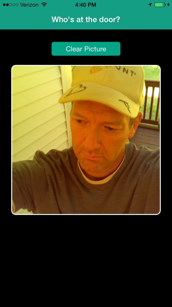
With all this in place, I build the app in Xcode and deploy it to my iPhone (remember, it must be a physical device because APNS doesn’t work with a simulator). My app screen looks like this:

Doorbell App – Initial Screen
I walk up to my door and press the doorbell button. The Node-RED flow on the Raspberry Pi takes a picture, stores it on the local file system and sends an MQTT message to the IBM Internet of Things Foundation broker. The Node-RED flow running on Bluemix in the cloud receives the message and tells the Raspberry Pi to upload the picture to the Bluemix Cloudant database. At the same time, Node-RED uses the IBM Push service, also running on Bluemix, to send a remote notification to the app on my phone. The app receives the push notification and presents an alert to me.

Doorbell App – Push Notification
I tap Ok to see who is at the door. The iOS app uses the IBM MobileFirst SDK to invoke adapter routines to first search for, then retrieve, the picture from the Bluemix Cloudant database. It then pops that picture onto my mobile screen so I can see who is ringing my doorbell, even if I am hundreds of miles from home and can’t do a thing about it.
Doorbell App – Someone at the Door
Conclusion
Well, that about does it. This has been quite an adventure. Clearly this isn’t an app you would put into production. I have over-engineered several areas and it is far more complicated than a doorbell needs to be. But we did get a chance to explore several technologies including:
- Setting up a Raspberry Pi with an external button input and a camera
- Node-RED visual editor for controlling and interacting with the Internet of Things
- Bluemix applications and services including Cloudant Databases, Node.js runtimes and mobile Push.
- Registering and app with Apple Push Notification Service.
- IBM MobileFirst Platform Foundation for enterprise security and access to Systems of Record such as Cloudant databases
- Using Xcode to create a native iOS application that receives push notifications from IBM Bluemix Push and retrieves data from Bluemix Cloudant datastores.
What’s next? Well, IBM just released MobileFirst Platform Foundation version 7.1 which supports deploying the MobileFirst server in a container in Bluemix – built on Docker technology. Maybe I will see if I can eliminate my local laptop entirely and have everything except the Raspberry Pi in the cloud!


