
This is part of a series of posts related to My Internet of Things and MobileFirst adventure. An index to all posts can be found at the end of the first post.
Now I have the Raspberry Pi running Node-RED and can control a pushbutton and LED. Cool. And then, the mail carrier came! My camera module arrived!
Camera module installation is pretty easy. Just follow the Raspberry Pi Documentation. There is an easy command-line utility called raspistill that I used to test out the camera.
Now there is no out-of-the-box node to control the camera module from Node-RED. I never found any Googling around the internet either. But that’s OK – this gave me an opportunity to see how extensible Node-RED is. I would have to integrate the Raspicam Node.js library into function nodes.
Making Raspicam accessible in Node-RED
First, I had to install the raspicam module into Node.js. Npm package manager makes that easy enough, but again, make sure you are in the right directory.
cd ~/.node-red
npm install raspicam
Now, that makes raspicam accessible in Node.js, but there is an additional step required to make it accessible within Node-RED. See the Global Context section in the Node-RED Documentation. In ~/.node-red/settings.js, I added
functionGlobalContext: {
        RaspiCam:require('raspicam')
},
Bounce Node-RED and you should be able to access raspicam commands inside Node-RED modules like
var camera = new context.global.RaspiCam( opts );
Adding a function node
Now I’m ready to add some code to control the camera. This is done with a function node.
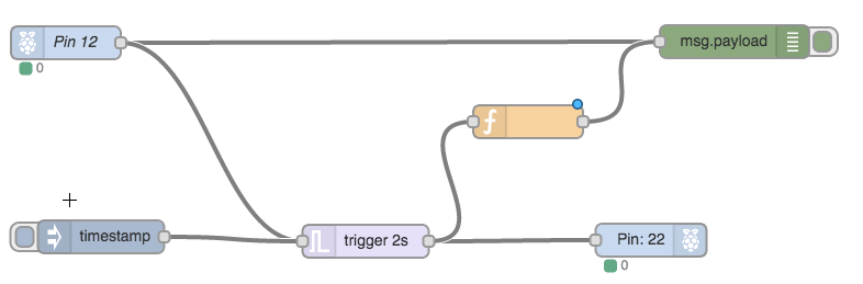
- Drag a function node onto the canvas and connect it like this

Function Node added to test flow
A couple things to note here. First, you can have more than one node wired to a node’s input. In this case, both the Pin 12 node and the function node will send information to the msg.payload debug node. We already saw this in the previous post because the Pin 12 node and timestamp injection node send output to the trigger node. Secondly, you can have more that one node take input from a node’s output. In this case, the trigger node will pulse the LED, but it will also send the trigger to the function node, which we will use to take a picture.
- Double-click the function node. Name it Take Picture. Paste the following code into the Function area:
// We only want to take pictures when
// the button is pressed, not when it is released.
if (msg.payload == 1) {
    var encoding = "png";
    var currTime = new Date().getTime();

    // Use the current timestamp to ensure
    // the picture filename is unique.
    var pictureFilename = "/home/pi/pictures/" + currTime + "." + encoding;
    var opts = {
        mode: "photo",
        encoding: encoding,
        quality: 10,
        width: 250,
        height: 250,
        output: pictureFilename,
        timeout: 1};

    // Use the global RaspiCam to create a camera object.
    var camera = new context.global.RaspiCam( opts );

    // Take a picture
    var process_id = camera.start( opts );

    // Send the file name to the next node as a payload.
    return {payload: JSON.stringify(
        {pictureFilename : pictureFilename}) };
}
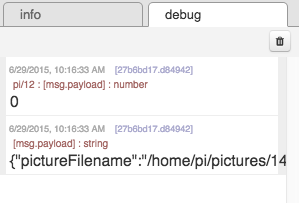
- Deploy the flow. You see two messages in the debug view. The first is the message from the Pin 12 node. The second is the message created by the “Take Picture” node. That node has told the camera to take a picture (if you were paying attention, you would have seen the red light on the camera module flash) and has sent a message with the filename to the debug node.

Deploy messages
There is a problem here. The Pin 12 node is configured with “Read initial state of pin on deploy/restart?” checked. This is causing my flow to trigger and a picture to be taken when I don’t want it to. I’ll fix that before verifying the camera worked.
- I’ll double-click the Pin 12 node and deselect “Read initial state of pin on deploy/restart?” and Deploy again. This time I get no new debug messages.
- Press the pushbutton on the breadboard. The camera light will blink as it takes a picture and the LED connected to Pin 22 will pulse for 2 seconds.
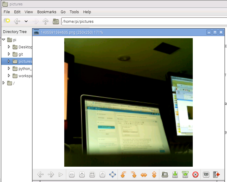
- I’ll open up a VNC session, find the picture file in /home/pi/pictures with the name in the debug message and open it. The picture isn’t all that exciting. My Pi camera is sitting on my desk, pointing toward my laptop monitor. But it proves that things are working.

Viewing picture on Pi VNC
Ok, so now I have a Raspberry Pi and a Node-RED flow triggered by an external button that will take a picture using the Pi camera module and store the picture in a file on the device. I’m making progress but so far I only really have a “thing”, not an “internet of things”. In the next post, I’ll set up my Node-RED environment on Bluemix so I have something to communicate with.

Pingback: My Internet of Things and MobileFirst adventure – Part 1 | Dennis Schultz's Blog
Reblogged this on Dinesh Ram Kali..